
Lead Edge Feeder Units
Feed-wheel positions that require reliable contact with the leading edge of corrugated board.
Precision-machined polyurethane wheels for stable sheet feeding and replacement projects, made after confirming OD, bore, width, hardness and mounting details.
Include OD, bore, width, hardness and quantity if available. See the quote checklist.
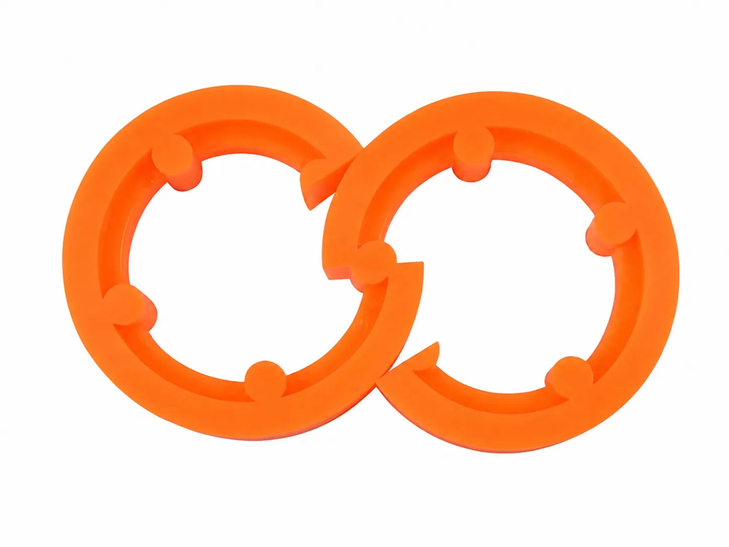
JUNSHIDA manufactures replacement lead edge feed wheels around the dimensions, profile and connection structure of the current component. Clear photos, a drawing or a physical sample help us review the correct configuration.
Final dimensions and structure are confirmed before quotation and production.
Polyurethane lead edge feed wheels help corrugated board enter the machine continuously and smoothly. Each replacement wheel is normally developed around the structure of the original machine part.
Feed-wheel positions that require reliable contact with the leading edge of corrugated board.
Stable feeding support for flexographic printing and carton converting lines.
Feed sections on slotting, die-cutting and combined printing-slotting-die-cutting machines.
Machine positions responsible for transferring corrugated sheets into the next process.
Custom replacements developed from old wheels, drawings, photographs or physical samples.
Feed wheels with machine-specific bores, pins, holes, hubs and contact surfaces.
We review the original component before confirming mold, material and finishing requirements.
Send machine information and clear photos of both sides.
Check diameter, bore, width, holes and drive details.
Review molding, hardness and finishing requirements.
Complete dimensional review, packing and shipment.
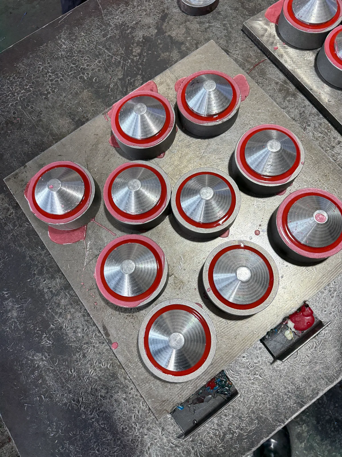
This production photograph shows red polyurethane feed wheels in their moulds. It documents the casting stage rather than the appearance of a finished replacement wheel.
For a replacement inquiry, share the wheel's outside diameter, bore, width and mounting details, together with photographs or a drawing of the original part.
Colour alone does not identify hardness or material specification. These details must be confirmed for the required application.
See the feed wheel measurement checklist →This part may be listed as a lead edge feed wheel, feeder wheel, paper feeding wheel or polyurethane feed roller. For a usable replacement, match the original connection geometry and working surface instead of relying only on a machine brand or product name.
The primary term for wheels that contact the leading edge and help introduce corrugated sheets into the next machine section. Bore, pins, holes, hub and face width are all application-specific.
A frequent search term for feeder-section replacements on corrugated box printing and slotting equipment. Share the complete machine model and installed position because one line can use several wheel designs.
Used when sourcing a replacement from the feeding section of rotary die-cutting equipment. Accurate sheet feeding depends on the wheel, machine setup and condition of the complete feeder assembly.
Record the actual symptom, board type, speed and current contact condition. Surface wear, hardness, pressure, timing or contamination can produce similar feeding problems.
Compare diameters across the installed wheel set and check shaft alignment, pin fit and surface condition. Replacing only one mismatched wheel may not correct an uneven set.
Confirm outer diameter, shaft bore, total width, drive-pin diameter and height, hole count and spacing, hub profile, contact surface and quantity. Include photos of both sides or send a sample.
A lead edge wheel is defined by its role and connection inside the feeder. A polyurethane sun or no-crush wheel usually provides more compliant conveying or guiding contact. Always identify the installation position before choosing either category.
For a buyer-ready dimension checklist, use the lead edge feed wheel measurement guide. For replacement planning, read the replacement guide. For unstable feeding, use the misfeed and sheet-skew troubleshooting guide.
These measurements and clear photographs help us confirm the correct replacement structure before quotation.
Measure the maximum outside diameter of the wheel.
Measure the center hole, shaft bore or bearing installation position.
Measure the full width of the wheel from one side to the other.
If fitted, measure each drive pin's diameter, height and position.
Provide the mounting-hole diameter, quantity, spacing and center distance.
Photograph both sides clearly to show the hub and installation details.
Show the contact surface, grooves, pattern or other surface details.
Provide the machine brand, model and installation position when available.
Yes. We can develop a replacement from the old wheel, a drawing, clear photographs or a physical sample.
Yes. Drive pins, mounting holes, hub structures, bores and other connection details can be customized.
The outer diameter, bore, overall width, hole positions, drive pin dimensions and mounting structure are the most important details.
Yes. Hardness can be adjusted according to feeding pressure, board type and machine operating conditions.
Yes. We check the dimensions, surface finish and structural details before shipment.
Yes. Suitability for a small trial order depends on the dimensions, mold requirements and production schedule.
Send wheel photos, outer diameter, bore, width, drive pin or hole dimensions, quantity and machine model so we can review the price more quickly.
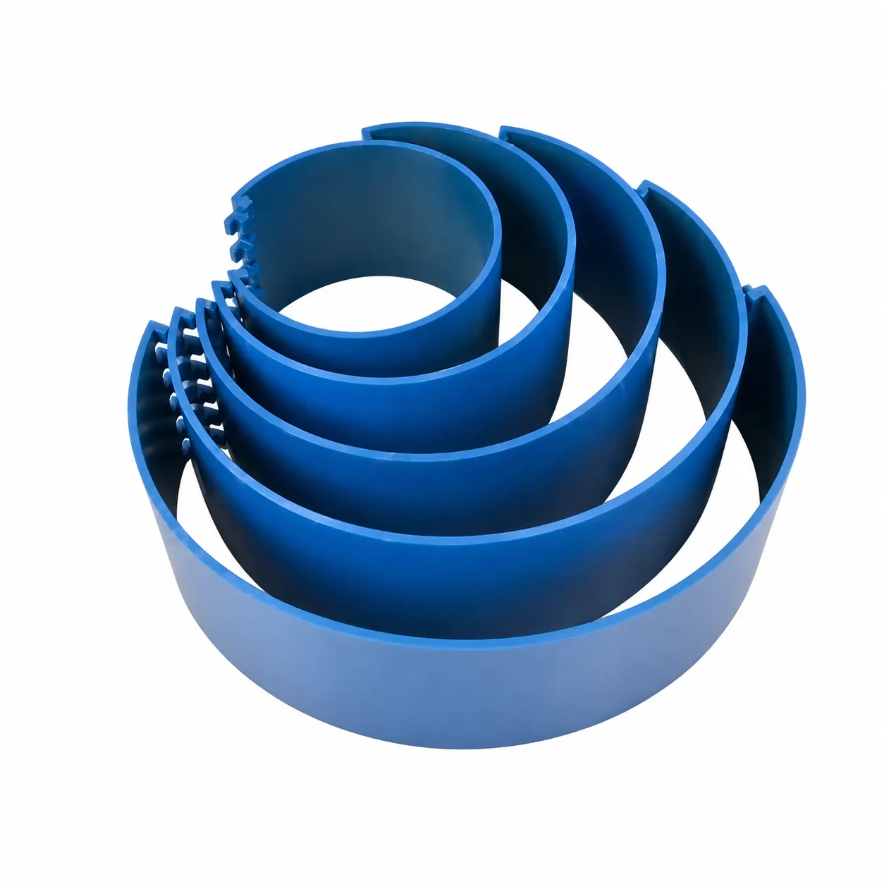
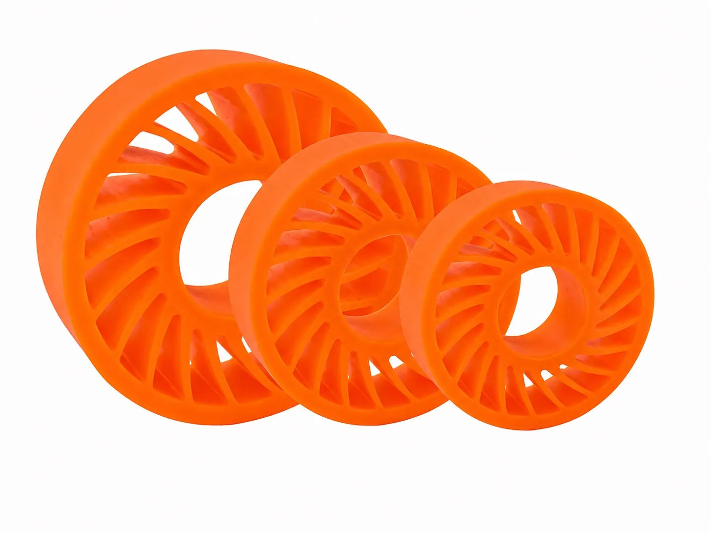
Confirm wheel dimensions, connection details and symptoms before comparing quotations.